01DEFINE
R&D & co-engineering
Requirements, feasibility and machine architecture. Mechanical and electrical decisions made together.
Requirements → Engineering concept
END-TO-END R&D & INDUSTRIAL AUTOMATION HOSUR, INDIA
Your end-to-end R&D and manufacturing partner—from mechanical, electrical, and PCB engineering to turnkey robotic systems.

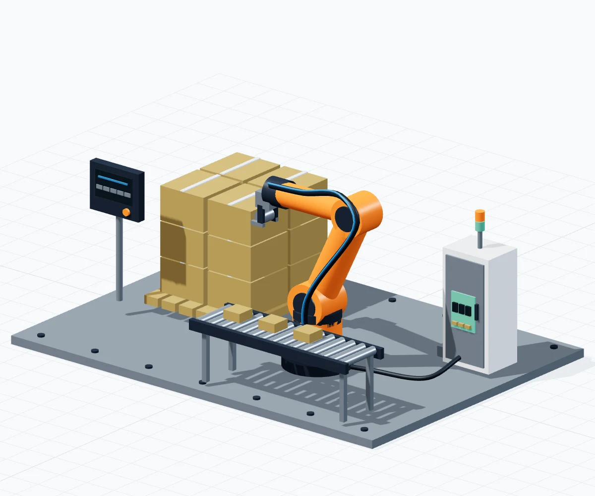
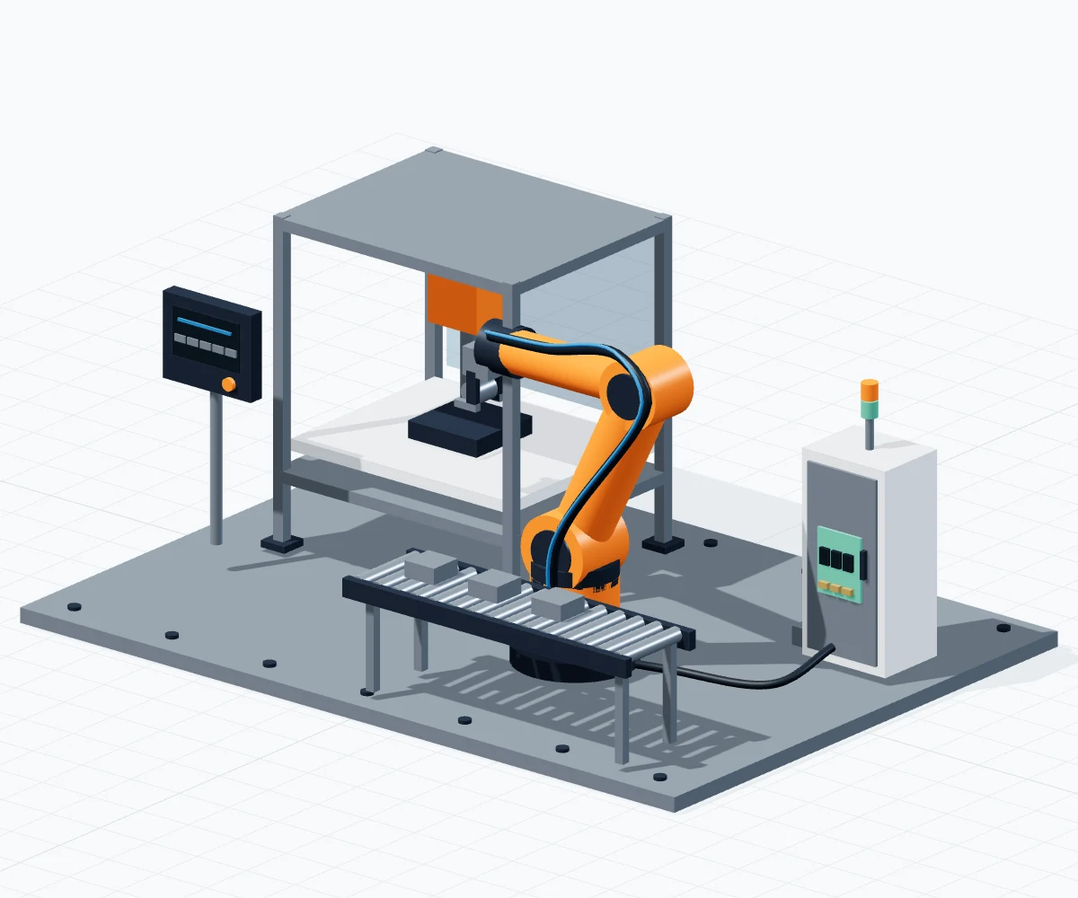
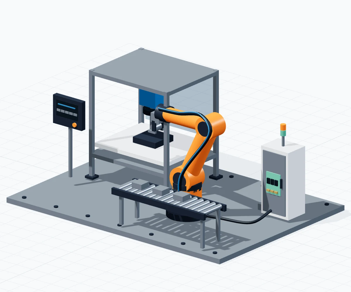
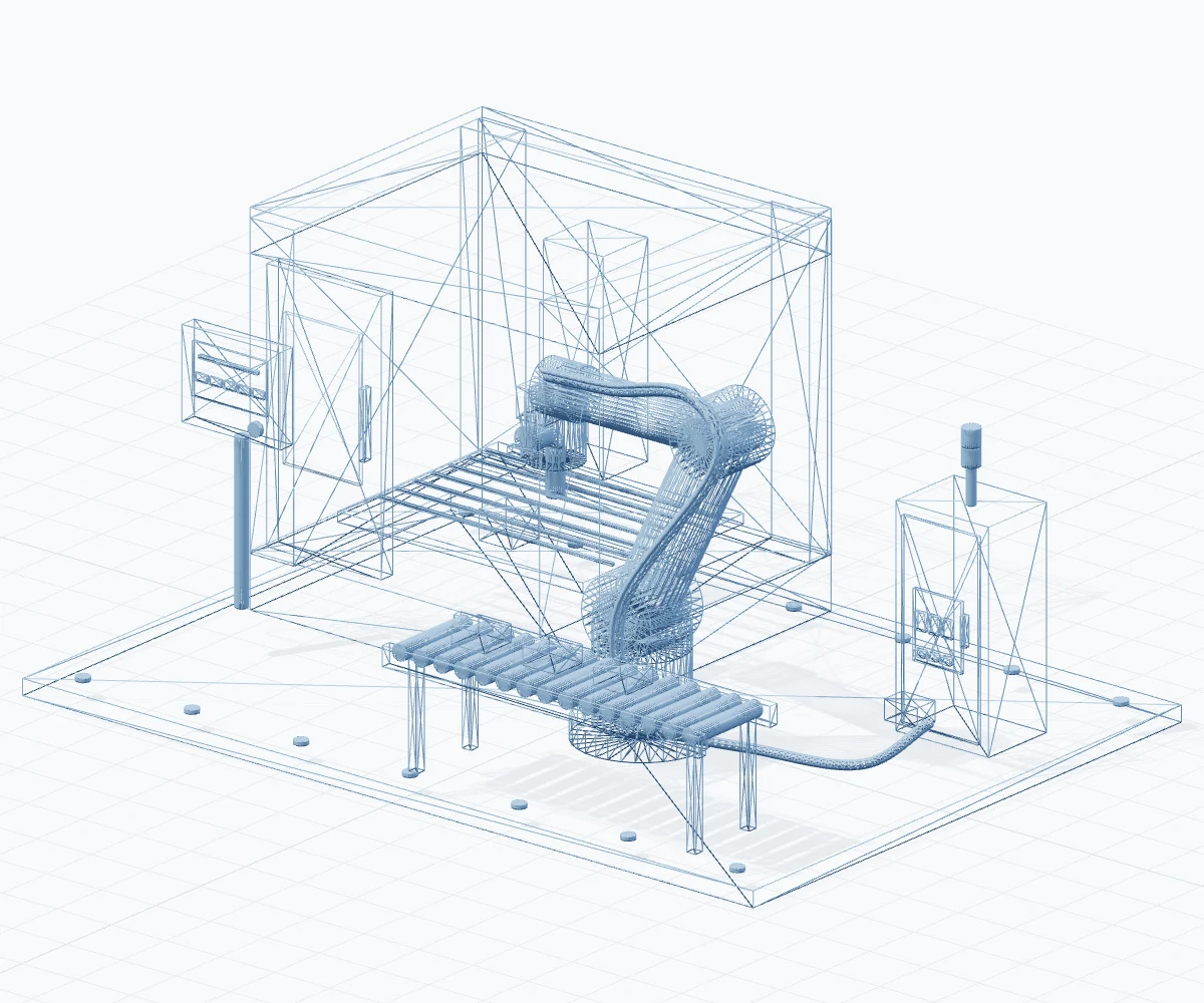
Build: illustrative assembly with material shading. This is a concept, not a verified installation.
This engineering concept connects a CNC machine, six-axis robotic arm, end-of-arm gripper, electrical control module, pneumatic lines and material conveyor. Design, verify and build modes use the same assembly and camera.
01 / UNDER ONE UMBRELLA
From first sketch to factory sign-off.
Connected disciplines. Buildable decisions.
The physical foundation. From machine architecture to the last locating pin.
Power, control and air. Engineered together, with serviceability in mind.
Check the assumptions before committing them to metal.
Bring the disciplines together. Build, integrate and test against agreed criteria.
FOUR DISCIPLINES. ONE ACCOUNTABLE PARTNER.
02 / CONCEPT TO COMMISSIONING
Requirements, feasibility and machine architecture. Mechanical and electrical decisions made together.
Requirements → Engineering concept
CAD checks, FEA where applicable, robot reach and collision studies. Test cycle-time assumptions before the build.
Digital model → Build decisions
Source, machine, fabricate and wire. Assemble, program and integrate the physical system.
Released drawings → Working hardware
FAT, installation, commissioning and SAT. Train operators and verify agreed acceptance criteria.
Acceptance tests → Production handover
03 / SHOP-FLOOR SYSTEMS
Designed around the workpiece.
Integrated around your process.
Robotic loading and unloading for CNC, press and molding machines.
Learn more about CNC machine tending ↗End-of-line handling, built around the product and available footprint.
Learn more about Robotic palletizing & packaging ↗Special purpose machines, test rigs, fixtures and integrated controls.
Learn more about Custom machines & R&D hardware ↗Camera inspection and robotic feedback for defined quality tasks.
Learn more about AI vision & closed-loop quality ↗ILLUSTRATIVE ENGINEERING CONCEPTS. FINAL SCOPE AND ACCEPTANCE CRITERIA ARE PROJECT-SPECIFIC.
04 / SIMULATION → REALITY
Simulation informs the design.
Physical testing closes the loop.
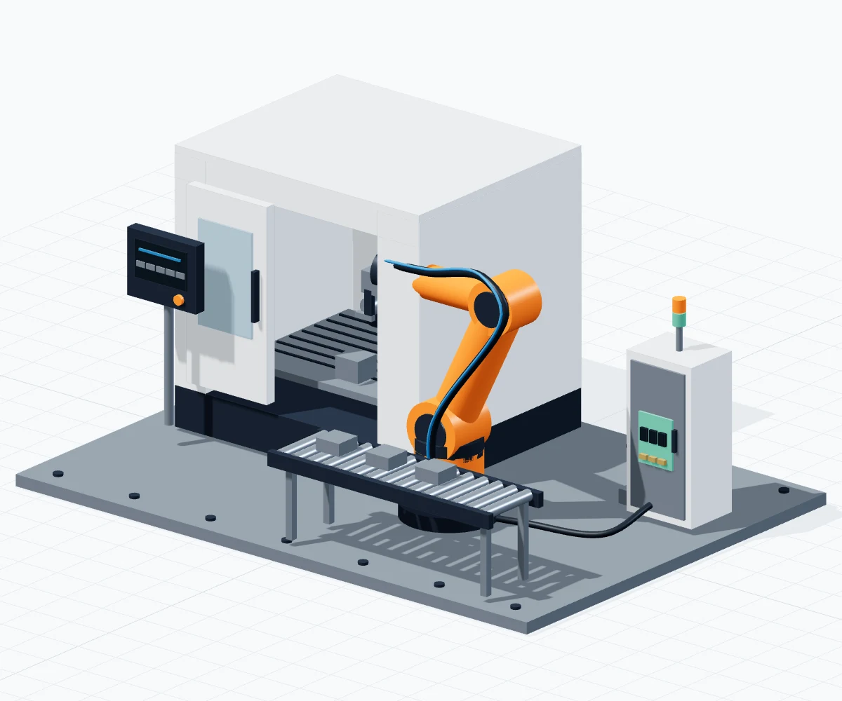
Drag to compare. Use arrow keys when focused.
Same assembly. Same camera. Illustrative concept, not a completed installation.
05 / LET’S BUILD WHAT’S NEXT
Tell us what needs to work.
A new machine. A demanding part. A process that needs a better way. Start with the engineering problem.
Hosur · Bengaluru · Chennai · Global